Visual Sound was an individual project completed as part of the ‘Gizmo: Physical Computing’ module, part of the Design Engineering (MEng) course at Imperial College London.
Inspired by needing to control the equalisers (EQs) of a track when mixing music (DJing), Visual Sound is a physical computing project where a physical representation of the various frequencies/pitches in a song are visualised.
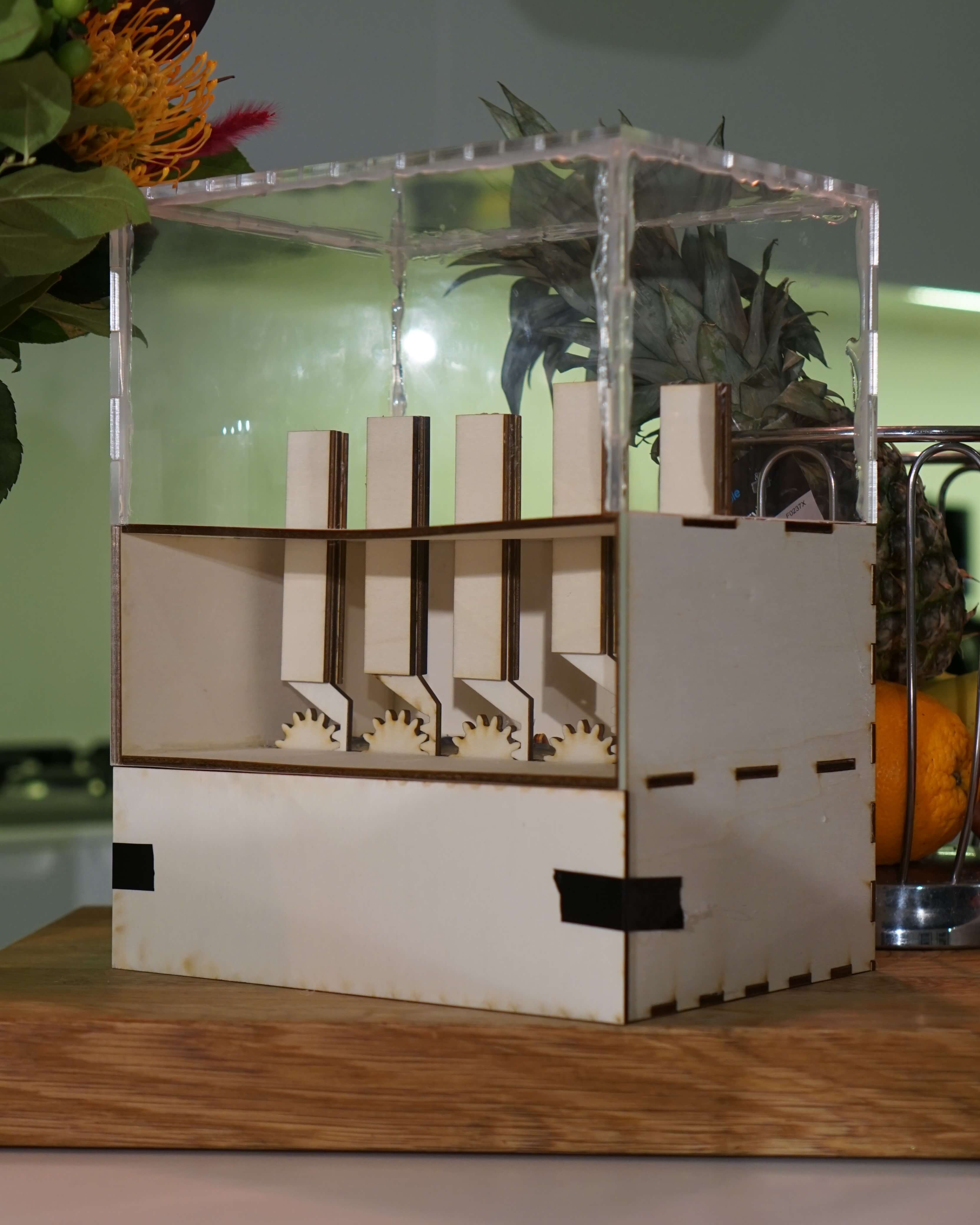
The 5 bars on Visual Sound represent the various frequencies in the music from bass (left) to highs (right), these move up and down depending on how much of that frequency (the intensity) is present in the sound at a given time. For example, if there is a strong bassline the left two bars will go up.
Visual Sound represent these different frequency bands in real-time so people can appreciate the different components of a song.
How it works
The 5 bars represent the frequency (pitch) range present within the sound, from bass (left) to treble (right). These move up and down depending on how much of that frequency (the intensity) is present in the sound at a given time. For example, if there is a strong bassline the left two bars will go up.
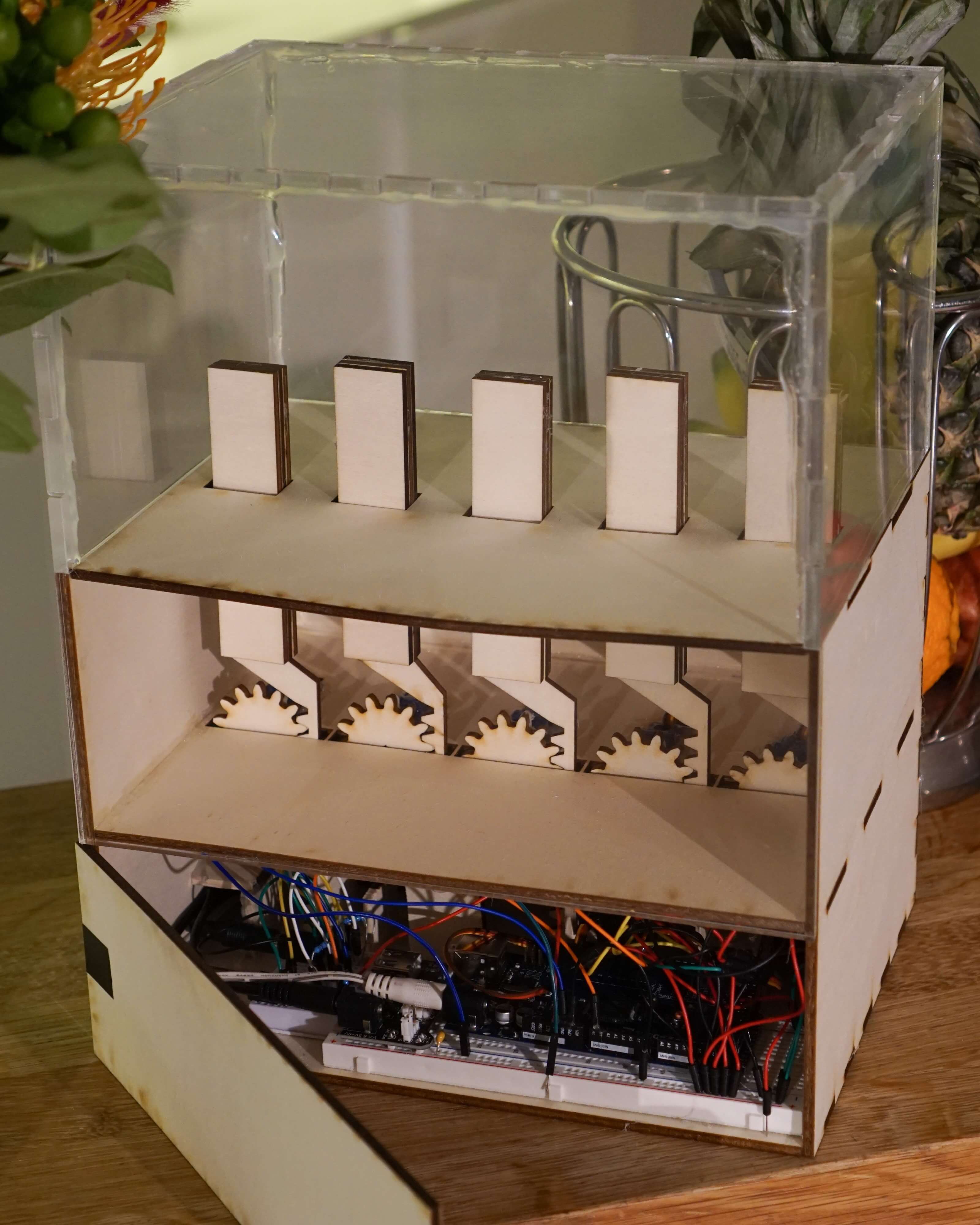
A rack and pinion mechanism is used to move the 5 frequency bars up and down. The gears (pinions) are connected to servo motors which turn in time with the music.
| Band | Frequencies (Hz) |
|---|---|
| 1 | 0-80 |
| 2 | 80-301 |
| 3 | 301-1131 |
| 4 | 1131-4255 |
| 5 | 4255+ |
The audio input pin is sampled (a snapshot is taken) at 40 kHz. The Arduino then repeatedly performs a Fast Fourier Transform (FFT) on the latest sample, this calculates the magnitude of the signal’s constituent frequencies. Intensities for each of the 5 frequency bands are then obtained by adding together the calculated FFT magnitudes of all the frequencies in a respective range. The servo motors are adjusted according to the magnitudes at a regular interval.
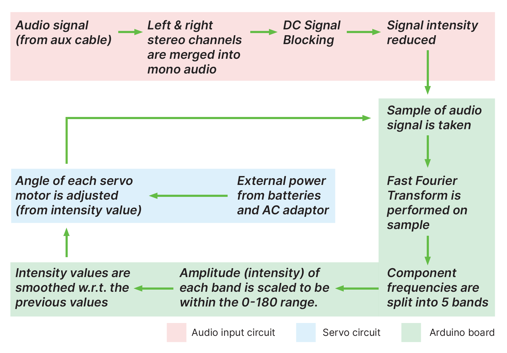 Visual Sound / System Diagram
Project development
Initial design
Initially after brainstorming and getting inspiration from other audio-reactive Arduino projects, I came up with an initial design (see sketch).
However upon reflection and discussing with my colleagues I realised that the rotary mechanism would involve unnecessary joints and moving parts, and that a rack and pinion mechanism would be better suited for my use case.
Issues with audio analysis
I initially wanted to use an MSGEQ7 chip to do the audio analysis (Electrical noise from servos). This is an integrated circuit (IC) that performs the frequency analysis analogical, meaning the analysis would not have been dependant on the processing speed of the Arduino.
However during testing on the breadboard I was unable to get any readings from the chip (multiple MSGEQ7 chips were tested) using the recommended circuit from the IC datasheet.
Subsequently I did additional research and found the FFT method which worked perfectly. No lag was experienced.
Electrical noise from servos
Once my audio analysis via FFT was working (suitable frequency magnitudes were appearing in the serial monitor), I tested controlling a servo motor with the data from one of the bands. To do this I connected the servo power cables to the 5V Arduino power pins.
As soon as the servo was connected, the circuit experienced huge electrical noise across the entire frequency spectrum, rendering the data meaningless.
When debugging I noticed that if I introduced an electrolytic decoupling capacitor across the power lines, this filtered out the noise in the high frequency bands while still allowing the FFT magnitude data to operate as normal in those bands. From this I determined that the noise was being transferred via the power lines.
Thus I tried powering the servos completely independently of the Arduino. This removed the noise completely and the servo responded to the audio signal as expected.
Laser cutting
Once my breadboard prototype circuit was working I was able to start constructing my Gizmo. For this I sketched out my parts on paper first and then made technical drawings in illustrator for the parts I wanted to laser cut.
This stage was largely pain free. However when laser cutting the clear acrylic hood/lid, I had to implement some trial & error to achieve the correct laser cutting speed to cut the material all the way through as this did not happen the first time around.